
Washer Type Load Cells
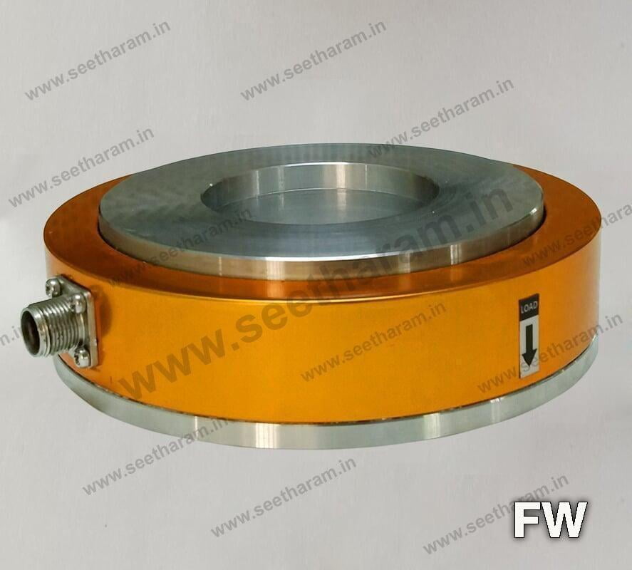
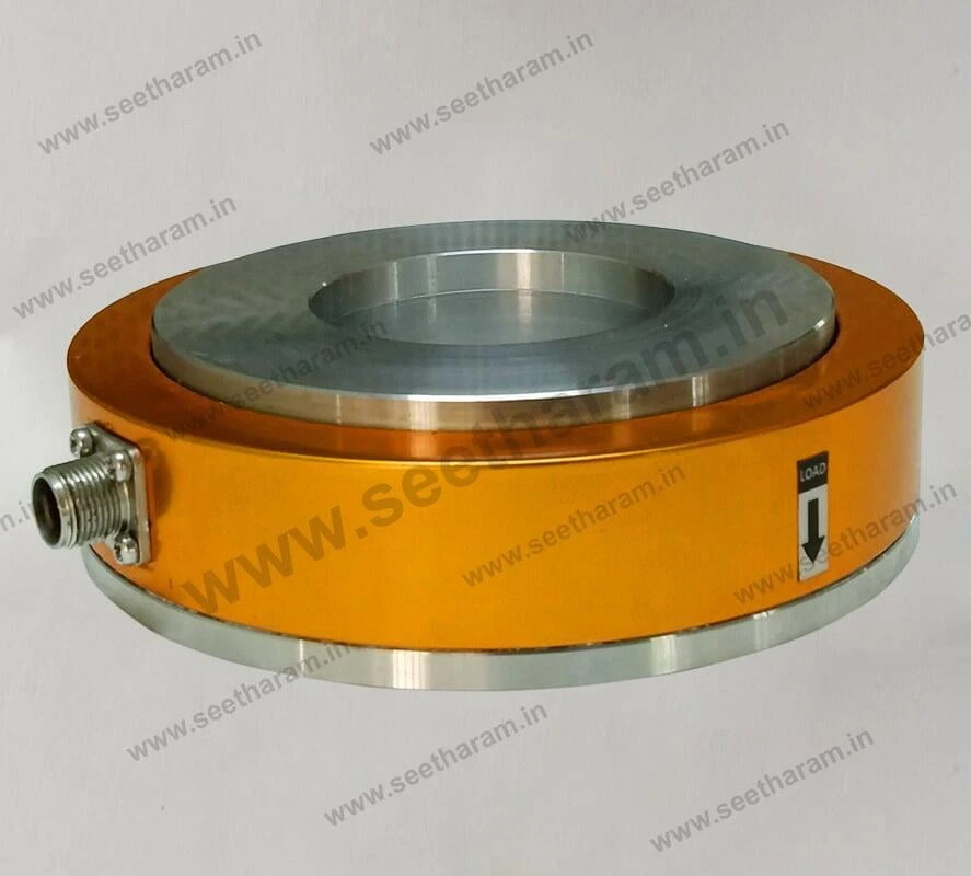
Force Washer Cell - FW
FEATURES
FEATURES
Washer type load cells with central hole are used for measuring force applied in their axial direction.
These washers find application for the indication and for the automatic control and feedback of axial thrusts static and dynamic on punching machines, on machine tools, on presses, on power hammers installed directly or, better, through a thrust spherical plane bearing.
MAIN CONSTRUCTIVE PECULIARITIES:
MAIN CONSTRUCTIVE PECULIARITIES:
- Low profile, compactness, high strength, easiness of installation.
- Central hole diameter: large, for standard metric shafts and screws.
- Internal sensors and electrical circuits: entirely stuffed by water-repellent and high insulating filler.
TECHNICAL SPECIFICATION
TECHNICAL SPECIFICATION
| Model | FW |
|---|---|
| Measuring ranges | 0.5tf ~ 10tf |
| Total error | lesser than ± 0.2% FS. |
| Sensitivity | 2 mV/V, typical. |
| Temperature effect on zero | lesser than ± 0.1 % FS. |
| Return to zero from FS | lesser than ± 0.1 % FS.) |
| Safe load limit | 50% over FS |
| Creep | lesser than ± 0.1 % FS. |
| Ultimate load limit | 2 times FS |
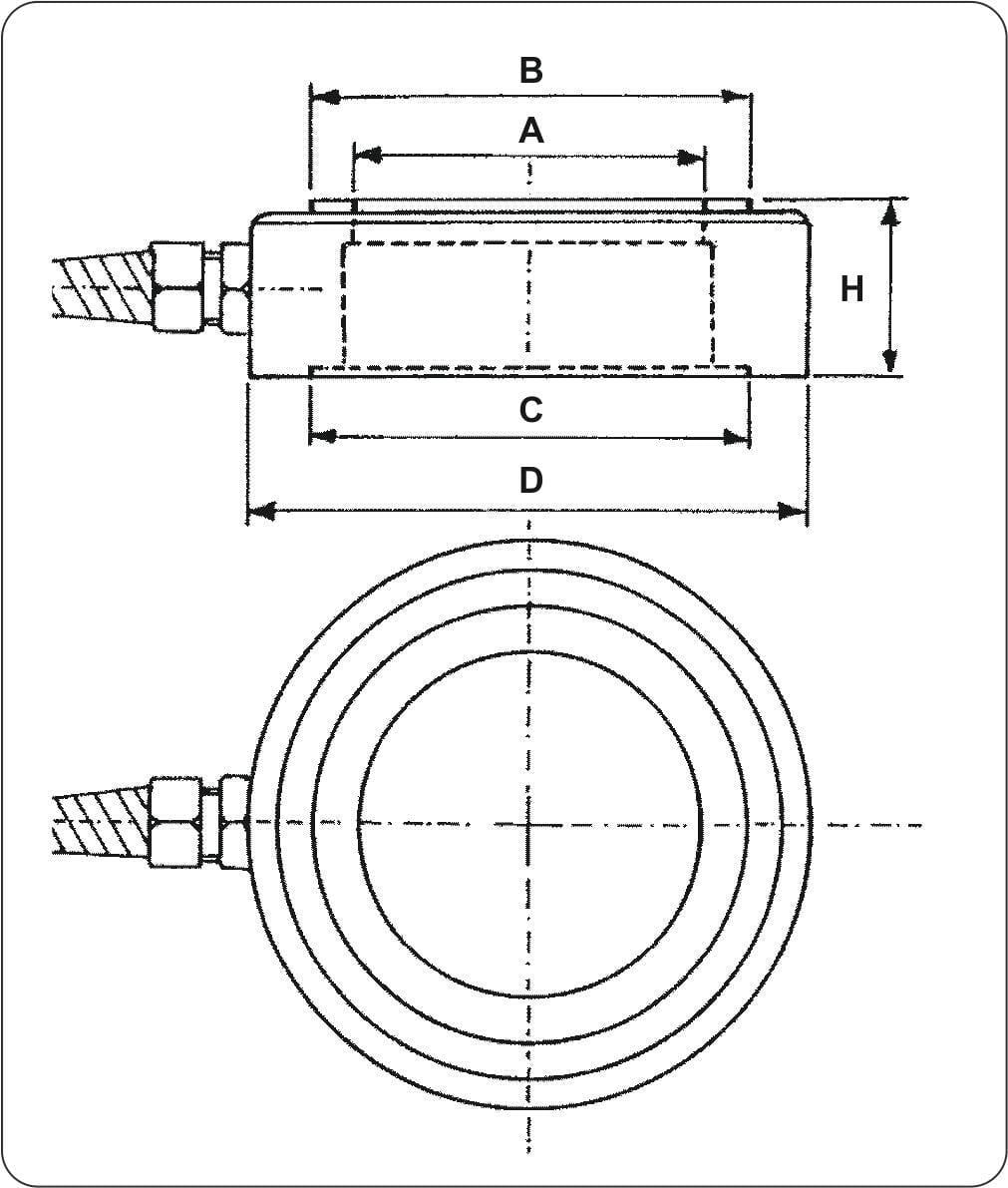
DIMENSION TABLE
DIMENSION TABLE
| Capacity | D | A | H | B | C |
|---|---|---|---|---|---|
| 0.5tf, 1tf | 49 | 10.1 | 26 | 34 | 44 |
| 2tf | 78 | 30.1 | 27.5 | 57 | 67 |
| 5tf | 98 | 40.1 | 29 | 75 | 79 |
| 10tf | 116 | 50.1 | 31 | 93 | 92 |
DIMENSION DETAILS
DIMENSION DETAILS
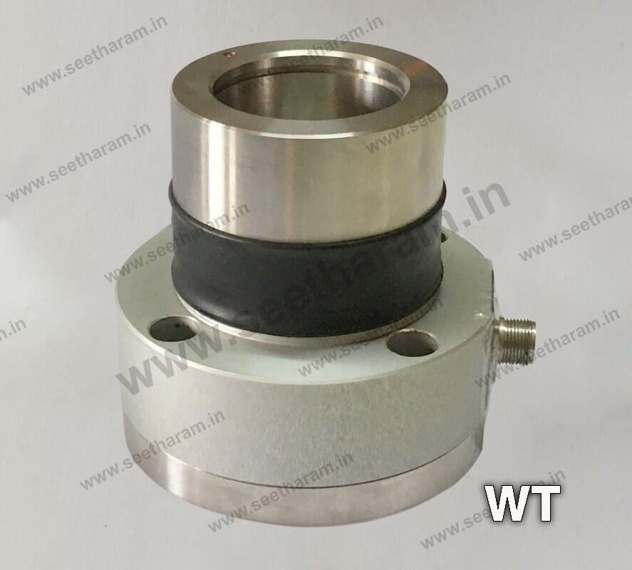
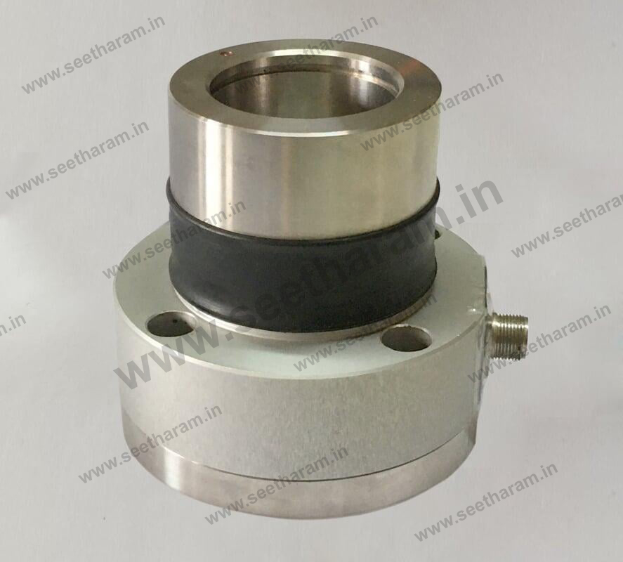
Web Tension - WT
Force Transducers for Measuring the Web / Spindle TensionFEATURES
FEATURES
- Range of measurement: from 100N to 2kN
- Accuracy class: 0.5%
- Corrosion resistant
- Internally generated calibration signal
- Orientation of the axis of maximum sensitivity for 35 independently from the position of the fixing holes
- Grade of protection: IP65 (DIN 40050)
- Integrated protection against overloads.
TECHNICAL SPECIFICATION
TECHNICAL SPECIFICATION
| Model | WT |
|---|---|
| Accuracy | 0.50% |
| Nominal full scale load (Ln) | 100N...2kN |
| Nominal output at FSO | 2mV/V |
| Output tolerance at Ln | lesser than ± 1% FSO |
| Combined errors: Non linearity,Hysteresis, Repeatability | lesser than ± 0.5% FSO |
| Creep (after 30 min. at Ln) | lesser than ± 0.06% FSO |
| Zero load out of balance signal | lesser than ± 1% FSO |
| Thermal drift in compensated range Sensitivity | lesser than ± 0.005% FSO°C |
| Thermal drift in compensated range Zero | lesser than ± 0.01% FSO°C |
| Thermal drift in compensated range Calibration | - |
| Nominal bridge resistance | 350 Ohm |
| Isolation resistance | > 10 G Ohm |
| Nominal supply voltage | 10V |
| Maximum supply voltage | 15 V |
| Compensated temperature range | -10...+50°C |
| Maximum temperature range | -20...+60°C |
| Storage temperature range | -30...+80°C |
| Permitted static load | 100% Ln |
| Maximum applicable load | 300% Ln |
| Rupture load | > 500% Ln [6 kN max.] |
| Maximum static lateral load | 150% Ln |
| Maximum elastic deformation at Ln | lesser than 0,5 mm |
| Grade of protection (DIN40050) | IP65 |
| Electr. connections: Connector | VPT02A10-6PT2 |
| Elastic element Material | Aluminium (100...1kN) Stainless steel (1.5kN - 2 kN) |
| Case Material | Anodised aluminium (Flange and bearing in AISI 303) |
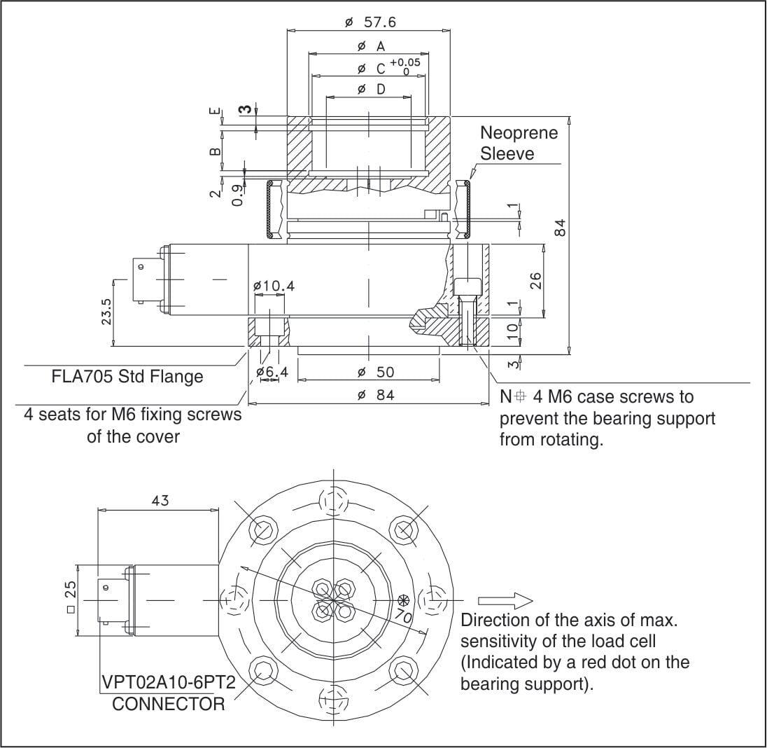
DIMENSION DETAILS
DIMENSION DETAILS
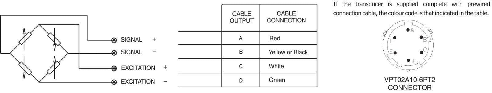
WIRING INFORMATION
WIRING INFORMATION
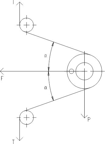
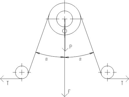
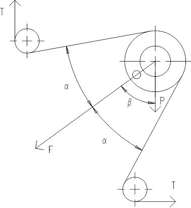
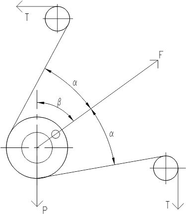
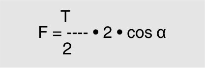
CALCULATION OF RESULTANT APPLIED TO CELL
CALCULATION OF RESULTANT APPLIED TO CELL
F = Resultant T = Tension in laminate P = Roll weight
The red point on the bearing support identifies the axis of maximum cell sensitivity and therefore the direction that F has to take with respect to the transducer.
| HORIZONTAL RESULTANT | VERTICAL RESULTANT | DOWNWARD RESULTANT | UPWARD RESULTANT |
|---|---|---|---|
 |  |  |  |
 | 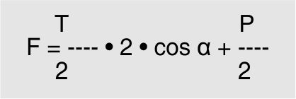 | 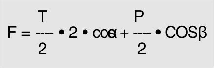 | 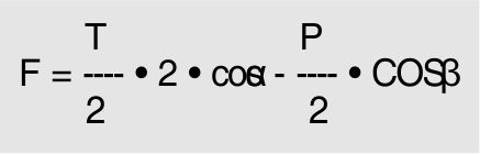 |
| This configuration gives the best performance because it does not consider roll weight. It is advised for low tension, to prevent roll weight from representing an excessive fraction of the resultant, with consequent reduction of the usable field. This is the only configuration in which, in the absence of tension T, there is a zero signal of approximately 0 mV/V. | In this configuration, roll weight is completely in the direction of maximum sensitivity of the cell that generates a signal in mV/V positive. This signal should be considered as tare: it will be considered during calibration of the instrument connected to the cell. | In this configuration, roll weight is completely in the direction of maximum sensitivity of the cell that generates a signal in mV/V positive. This signal should be considered as tare: it will be considered during calibration of the instrument connected to the cell. | In this configuration, roll weight is completely in the direction of maximum sensitivity of the cell that generates a signal in mV/V negative. This signal should be considered as tare: it will be considered during calibration of the instrument connected to the cell. |